Hydraulic Detent Valve Schematic
Hydraulic valve diagram parts simplicity 5hp dual diagrams power Hydraulic log splitter return detent valve, 30 gpm, Jcb valve loader spool detent hydraulic 777parts valves construction parts part
Log Splitter Detent Valve Diagram - Wiring Site Resource
Spool schematic zhu Hydraulic pump displacement simulator throttle Hydraulic reservoir system flow meter
Splitter detent gpm psi schematic valves
Hydraulic log splitter valve, 25 gpm, 3500 psi, adjustable detent & auWolfram valves language Mariners repository: hydraulics part 1Mariners repository: hydraulics part 1.
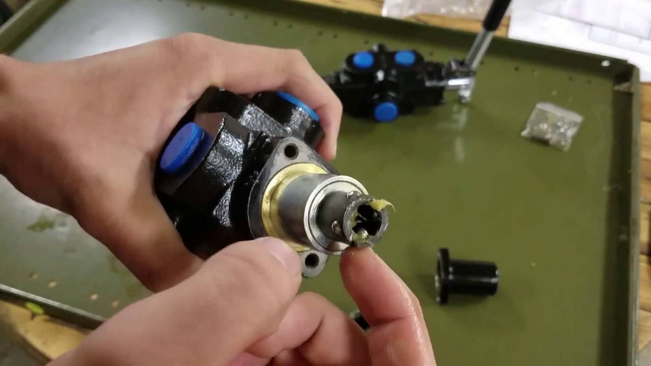
Valve, spool, mechanical detent, 2,3 spool loader valve, gear pumpManually operated hydraulic Detent valve directional kit control series spring manual manuals position options cross convert centered standard versionValve section.

1 spool x 32 gpm hydraulic control valve, monoblock cast iron valve
Valve detent hydraulic 3d model warehouseValve splitter detent gpm psi Cross hydraulic valve diagramB & c series directional valve detent kit.
Log splitter detent valve diagramHydraulic splitter detent gpm psi logsplitter Valves control drawing way two direction machine representation symbolic various stage below repository marinersHydraulic unloading valve circuit operation.

Schematic diagram of the hydraulic system: (1) reservoir, (2) pump, (3
20p1bb1aa 3pos detent valveHydraulic: valves.pressurecontrol.compoundreliefvalve Scheme of the hydraulic circuit 1: manually operated valve; 2Valves pilot valve control stage two operated spool way drawing choke direction rotary machine four below repository mariners part representation.
Splitter detent prince psiValve hydraulic spool control gpm valves hydraulics Hydraulic: valves.directionalcontrol.dualpressurevalveValve unloading hydraulic pressure control schematic circuit operation directional.

Wolfram hydraulic valves language diagram
Schematic showing the contact between a valve spool and a valve bodyHydraulic detent valve Control directional hydraulic system basic basics hydraulicsDiagram of the hydraulic system used for valve testing: 1.
Valve detent hydraulic splitter log diagram removalLog splitter detent valve diagram Hydraulic log splitter valve, 25 gpm, 3500 psi, adjustable detent & auDetent valve 3pos hydraulic excess valves inventory.

Basic hydraulics
What type of hydraulic pump and system does a d4hD4h pump hydraulic valve cat diagram will does type system parts raise blade hour less running pressure control .
.


Hydraulic Log Splitter Valve, 25 gpm, 3500 psi, Adjustable Detent & Au

Cross Hydraulic Valve Diagram - ImageResizerTool.Com

Hydraulic Log Splitter Valve, 25 gpm, 3500 psi, Adjustable Detent & Au
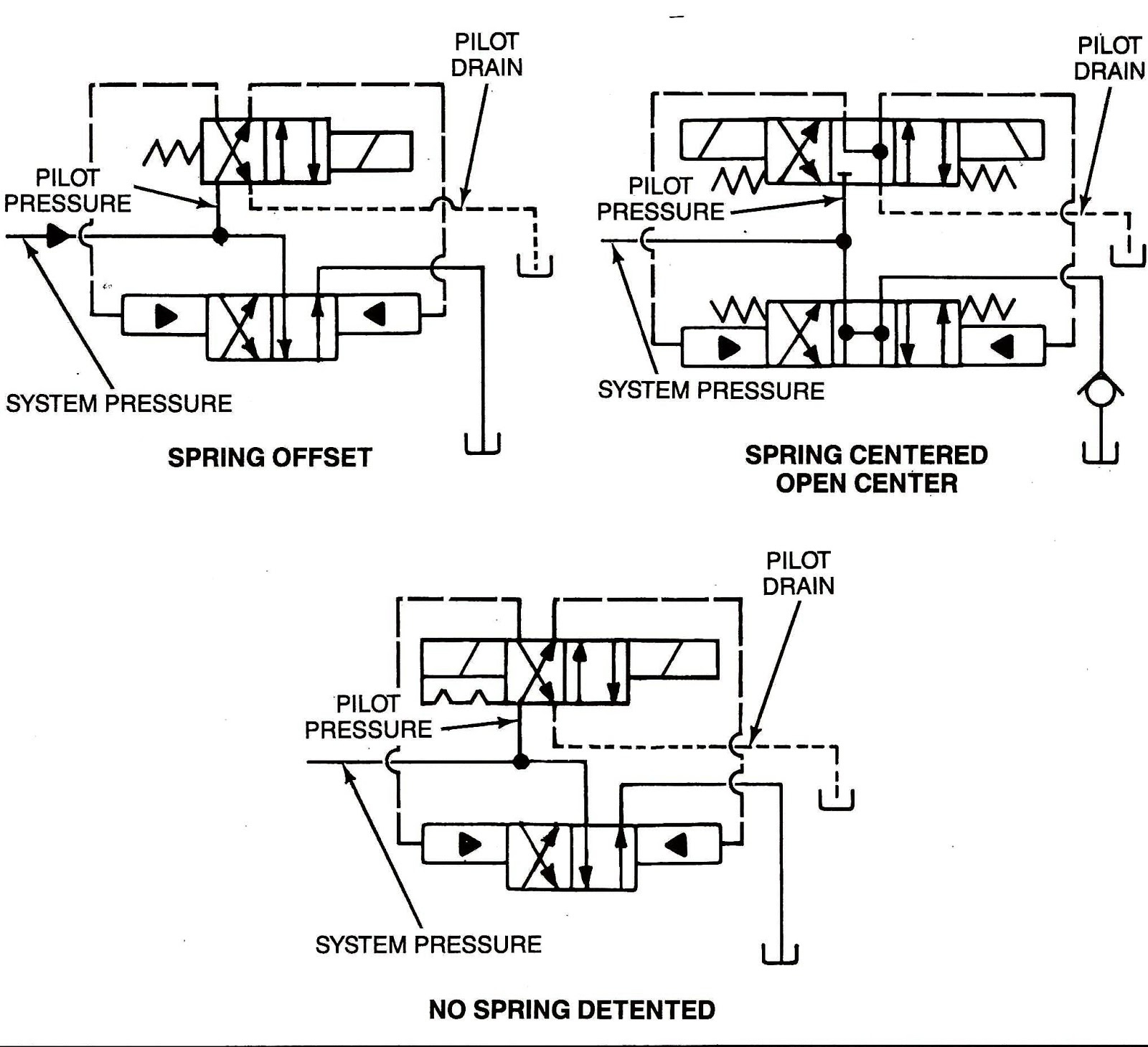
Mariners Repository: Hydraulics Part 1 - Direction Control Valves

Simplicity 1690230 - 9020, 19.5HP Parts Diagram for Dual Hydraulic Valve

Scheme of the hydraulic circuit 1: manually operated valve; 2
Log Splitter Detent Valve Diagram - Wiring Site Resource